
In this post we’ll look at the construction of low latency carry save adders (CSAs) and compressor trees for use in a low latency MSU. These structures comprise the bulk of the Öztürk design. In the architecture drawing below both the white and red upside down triangles and the turquoise rectangle are nearly 100% compressor trees, accounting for >80% of the logic in the design.

Compressor Trees
Compressor trees perform the function of accumulating an array of numbers into a final redundant sum in a low latency manner. In our case the function we’re interested in is (in pseudo python):
A = [ x0, x1, …, xn] # x0 .. xn are 16-bit unsigned integers
sum = 0
for i in range(len(A)):
sum = sum + A[i]
Because we need low latency it is not sufficient to sum the values in series as implied by the code. This section will walk through the techniques needed to achieve low latency using compressors, trees, and redundant representation.
Bit-level compressors
At the lowest level a compressor takes as input a small number of input bits and sums them, producing a redundant carry and save output. Common compressor sizes are 3:2, 4:2, 7:3, and 9:4. The page ASIC Design for Signal Processing describes these bit level compressors in more detail. We combine these bit level compressors to form carry-save adders, which use a redundant representation to reduce the latency of adding 3 or more inputs.
Low latency adders
If you are not familiar with adders in general our previous blog post may be of interest. In that post we looked at the implementation of low latency adders and considered a variety of adder structures.
Recall that the key challenge with building low latency adder circuits is handling carries. The basic approach to adding two numbers is called a ripple carry adder and matches what you learned in school. Carries from one column are immediately propagated and summed into the next column. This creates a serial chain of carry dependencies as long as the width of the number, leading to high gate depth and slow circuits.
The following drawing shows a 4-bit ripple carry adder with a full adder depth of 4 (C1 through C4):

“4-bit ripple carry adder made up of four 1-bit full adders” by Cburnett (Own work) CC BY-SA 3.0
Carry save adder: A carry save adder on the other hand breaks the carry chain by using bit level compressors to sum two numbers with no carry propagation. With this approach summing two numbers always has the same latency, regardless of the data width.
A 4-bit carry save adder has a full adder depth of 1 for any bitwidth, as shown:

One thing to take into account with carry-save adders is that they produce two outputs, carry and sum, instead of a single sum. Our final design compensates for this by using a carry propagate adder (CPA) to produce a single result, but we only need to do this once at the end rather than at every stage of the tree, a big latency saver.
Compressor trees
The Ozturk design requires accumulating large numbers of polynomial coefficients in both the squaring and reduction portions of the design. For a 2048 bit modulus and 16 bit coefficients we need to accumulate ~1200 16-bit multiplier partial products in the squaring portion of the design and ~1100 coefficients in the reduction portion of the design. If done serially using carry-save adders this would result in an adder depth of ~1200 and a very slow circuit.
The following drawing shows an example for serially adding 8 inputs:
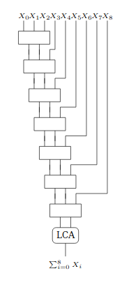
Instead we can take advantage of the commutative property of addition and structure these additions into a tree of log(n) depth, as shown below. In this case the levels of carry-save adders for 8 inputs drops to 4:

In this study we analyze the compressor trees required for the Ozturk design and begin to look at implications for the full MSU design.
Study Approach
For this study we chose sizes that correspond to the 2048-bit Öztürk design, but we expect the results are applicable to compressor trees in general.
The Intel white-paper Large Integer Squaring on Intel® Architecture Processors provides a good general background on large integer multiplication and squaring techniques. To illustrate with small numbers, suppose the task is to square a 4-digit number. The drawing below shows the schoolbook multiply adapted to a squaring operation.

First the partial products are generated by multiplying the individual digits together. Each result is inserted in the appropriate column, then the columns are summed (using compressor trees) to produce the product, which is twice as wide as the input. When squaring, the two operands are the same, therefore the light purple partial products will appear twice (for example x0*x1 and x1*x0). Rather than add them twice we optimize by generating these partial products once and then double the result, which is simply a 1 bit shift left in hardware.
In our case we assume 16-bit digits and 130 coefficients, leading to compressor trees of depth ~1200 in the middle columns. For reduction we have a nearly constant depth of around 1100 inputs, with some variation depending on the particular fixed modulus.
Given a compressor tree size we can then either consider it as a monolithic block or compose it from smaller building blocks. Functionally the approaches are the same but there are physical and tool implications, including:
The ability of the tools to optimize a design of the given size. Above a certain size and complexity runtimes become prohibitively long and the tools tend to do less well finding ideal implementations.
The power, performance, and area implications of replicating thousands of a small core design vs. optimizing individual columns specifically for the number of inputs they need to sum.
The opportunity to spend significant effort optimizing a single cell that is leveraged many times (perhaps using custom cells) vs. spreading that effort around.
In this case we consider 3 cases, a 1-level compressor design, as well as a 2 or 3-level balanced design. We use the term balanced tree to mean choosing a compressor size such that the number of inputs and therefore the latency consumed at each level are approximately equal. This leads to the following sized trees:
1-level compressor: 1224-input x 17-bit
2-level compressor: 72-input x 17-bit
3-level compressor: 22-input x 17-bit
Impact of Performance on Power
Minimizing latency has a cascade of effects that result in large power increases. These come from insertion of more low voltage threshold (VT) devices, larger drive strength, higher voltage, and higher leakage. Specifically:
ULVT (ultra-low voltage threshold) devices replace LVT (low voltage threshold) and SVT (standard voltage threshold) devices in the critical path. ULVT devices transition faster at the expense of higher power and leakage.
Drive strength, which is the ability of gates and transistors to transmit current onto a wire, increases. This increases power and area.
Voltage is increased for higher performance, increasing power.
Higher voltage increases leakage current and leads to higher temperatures, which further increases leakage.
These factors mean that minimizing latency comes at a high cost in power and heat.
Study Results
Compressor Construction
To start we explored building compressor trees using a variety of bit level building blocks (compressors of size 3:2, 4:2, and 7:3) and tree styles (Wallace, Dadda). Like in the CPA study, these differences had little impact on the final outcome. By default the tools look through the hierarchy and apply transformations that reshape and improve the circuit. When the tools are forced to keep the structure intact the resulting circuit performance is somewhat worse.
We also compared these designs to simply using a series of “+” operations to sum many inputs. There are two big potential pitfalls with this approach:
If the tools treat it as a long linear chain instead of forming it into a tree then latency would be very bad.
If each “+” is implemented as a carry propagate adder then the carry chain latency would be very long, exactly the problem we hope to avoid by using carry save adders.
It turns out neither of these pitfalls occurs. When coded using “+” the tool is able to recognize the arithmetic function and apply specialized arithmetic optimizations that target low latency. Specifically, it creates a tree structure and uses carry save adders internal to the tree to keep latency low.
In the end, the results using an explicit tree and a series of “+” operations are shown in the table below:
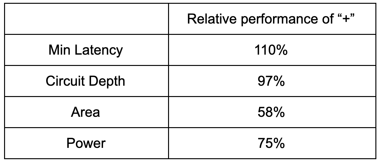
Relative performance of a compressor built with a “+” operations vs. an explicit tree structure with bit level compressor cells
As can be seen, the minimum achievable latency was slightly better using the bit level implementation, while the other metrics were worse. Given these similarity of the metrics and the simplicity of the “+” based approach, the “+” based approach is preferred. Interestingly, similar experiments with FPGA designs showed worse performance using the “+” approach vs. the bit level approach due to the heavy use of carry propagate adders.
Compressor Size and Number of Levels
Having determined the best way to code the compressor trees, we next looked at building a 1224-input compressor tree in 1, 2, and 3 levels. Our reasoning for trying a multi-level design was that smaller building block circuits might allow the tools to do a better job in optimizing this core component, which could then be repeatedly tiled.
The following table shows the results for the various trees at the lowest achievable latency. Latency, area, and power are relative to a 1-level design baseline, and encompass the compressor trees needed for both the squaring and reduction parts of the design. The instance count shows the estimated number of trees required in a full 2048-bit square-reduce design.

And in chart form:

The 1-level design is clearly better for latency and power. Area is slightly worse for the 1-level design, but this is not a big concern as the incremental silicon cost is a marginal price to pay for improved power and performance.
Building on the themes from this and the previous blog, we believe the 1-level design does better because the tools are able to optimize for the entire circuit. In constructing larger trees from smaller components, each of the smaller components has a critical path driven by the low latency cells. This critical path is built with low voltage threshold cells with larger drive strengths in order to meet timing. However, once tiled together into larger trees, most of these paths are no longer critical in the larger circuit, meaning that the increased performance and power goes to waste. Further, the actual critical path of the larger circuit may not fully align with the fastest paths in the smaller components, resulting in a longer latency.
These results point us in the direction of focusing on the 1-level compressor tree design rather than a multi-level design, thereby giving the tools the most opportunity to optimize.
Conclusions
In general special care is not needed to build low latency compressor trees for ASICs — “+” is sufficient. The tools are very good.
A 1-level tree design is preferred over a 2 or 3-level design.
It is preferable to synthesize each compressor tree for the exact number of inputs needed rather than tiling out a larger tree from smaller components. This results in significant area and power savings.
Source Code
Source code for the designs presented here are available on GitHub at supranational/hardware and is licensed under the Apache 2 license.
Acknowledgements
We’d like provide a special acknowledgement to Synopsys® for their support of this work.