
Adders play an important role in any multiplier design, including the Öztürk design. There are two types of adders used in the design:
Carry Propagate Adders (CPAs) take some number of inputs and compute a sum by fully propagating the carries. The adders taught in elementary school fall into this category. Wikipedia provides a nice overview.
Carry Save Adders (CSAs) take some number of inputs and produce two redundant outputs, sum and carry. Producing two outputs means the carries do not have to be propagated, an important latency consideration. Wikipedia also provides an overview of these.
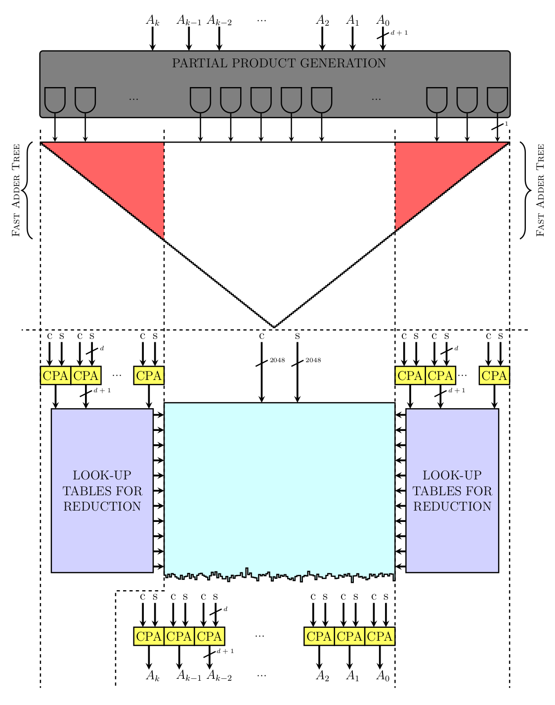
CPAs are used sparingly in the Öztürk design to minimize latency but do show up in two places (yellow boxes), at the bottom of both large CSA trees (red triangles). In both cases they are used to reduce the carry and sum the outputs of the CSA trees into a single value that can be used for reduction and squaring. The white portion of the squaring CSA can produce a result in carry/sum form that flows straight into the reduction CSA, without any CPA needed.
In this post we’ll look at the construction of low latency carry propagate adders. These have been well studied in the past but we wanted to have a fresh look for a couple of reasons.
Our target of lowest latency possible is pretty unusual in the silicon industry. Typically designs target a balance of latency and throughput.
It’s difficult to find published work based on recent process technology. We hope to fill some of that gap in this blog.
The data for this and subsequent posts is derived from synthesis runs using modern tools and processes.
Carry Propagate Adders
A key challenge with building low latency adder circuits is handling carries. The basic approach to adding two numbers is called a ripple carry adder and matches what was taught in high school. Carries from one column are immediately propagated and summed into the next column. This creates a serial chain of carry dependency as long as the width of the number, leading to high gate depth and high latency circuits.
The following drawing shows a 4-bit ripple carry adder with a full adder depth of 4:

“4-bit ripple carry adder made up of four 1-bit full adders” by Cburnett (Own work) CC BY-SA 3.0
You can also watch an animation of a ripple carry adder in action.
Fortunately there are techniques to reduce the gate depth at the cost of additional logic. We implemented several parallel prefix adders, which are a form of carry lookahead adder, and explored their use in this design. Some references to consult for more detail are the slide set by Kostas Vitrooulis and the paper “A Taxonomy of Parallel Prefix Networks” by David Harris.
In this study we’ll compare the performance of adders consisting of ripple carry, Brent Kung, Kogge Stone, and “+” (i.e. write “a + b” and leave it to the tool to figure out).
Optimization Goals — Power, Performance, Area (PPA)
The main metrics to consider are power (watts), performance (ns latency), and area (mm²).
Theoretically we would expect to see something along these lines:
Ripple carry — slow (long carry chain), low area (minimal replicated hardware), lower power due to less hardware
Brent Kung, Kogge Stone — fast, higher area (replicated logic to compute carry), higher power
+ — unknown, dependent on what the tool does
The following data is all presented in relative terms using a 16-bit adder as the test case. We use “+” as a baseline (1.0) and compare the relative performance of the other implementations.
PPA Measurements
Performance: Performance for VDF evaluation is improved by reducing the time time it takes to perform a modular squaring, often measured in nanoseconds. To evaluate the lowest latency for different adder designs we swept a range of clock periods and looked for the shortest period with no negative slack, i.e. that met the timing goal. What we found is that in spite of significant differences in tree depth as coded in RTL, the results were all within the margin of error. The synthesis tool did a good job of taking apart the function and optimizing it to meet design targets.

Power: In fact, we saw similar results for power…

Area: and area.

What uniform results! In all cases the design was transformed by the tool into a circuit that would meet the constraints. These results indicate there is little reason to use anything other than “+” to build adders. In fact, “letting the tool do its job” will be a common theme as we go forward.
A Retrospective
The tools have not always been this clever and historically would benefit from some implementation guidance. As an example here are results for a ripple carry adder with the latest generation of optimizations disabled. You can see it built a nice small, low power adder but was not able to transform it into a low latency adder.
Power and Performance
One interesting thing from the previous graph is that the relationship between power and latency is non-linear. In that case, latency increases by 2.3x while power decreases by 5x.
In the following graph we sweep latency and look at the resulting power compared to a target (100% latency). You can see that as latency goes down power rises and eventually hits a knee where it rises very steeply. As latency drops below 40% the tool is no longer able to meet the target (i.e. there is negative slack) and the power climbs a little less steeply.

Conclusions and Code:
A few points to take away as we wrap up this post:
In general special care is not needed to build small low latency adders — “+” is sufficient.
The latest generation of tools is very good at optimizing and refactoring logic. It’s better to let them do the work.
Power increases quickly as latency decreases. This is not a surprise as the high performance chip industry (CPUs, GPUs, etc.) has been heavily focused on power for about two decades. Power will play a big role in this design too as we push for the lowest possible latency.
Upcoming Posts
In the upcoming posts we will dive into more detail on designing a low latency MSU by exploring:
Carry save adders (CSA) and compressor trees
Partial product generation (PPG)
Ideal coefficient bitwidth
Complete MSU design
Source Code
Source code for the designs presented here are available on GitHub at supranational/hardware and is licensed under the Apache 2 license.
Acknowledgements
We’d like provide a special acknowledgement to ePIC Blockchain for their feedback on implementing high performance CPAs and to Synopsys® and Dolphin Technology for their support of this work.